


|
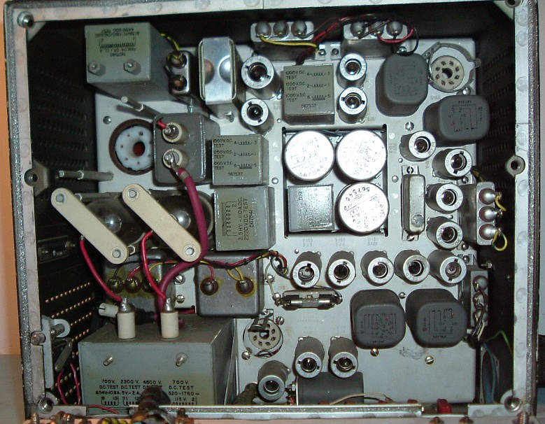
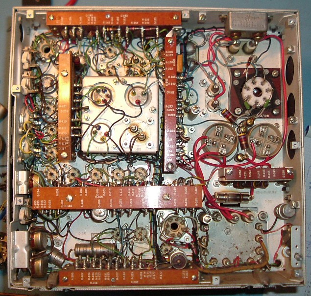
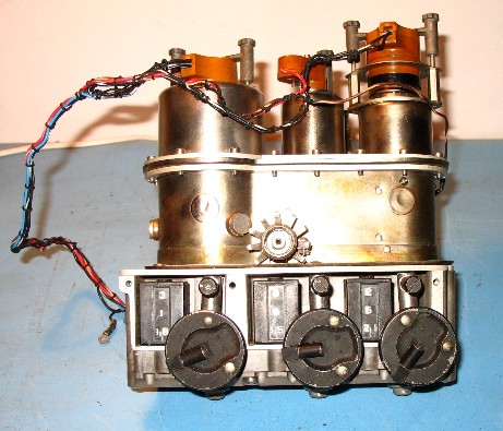
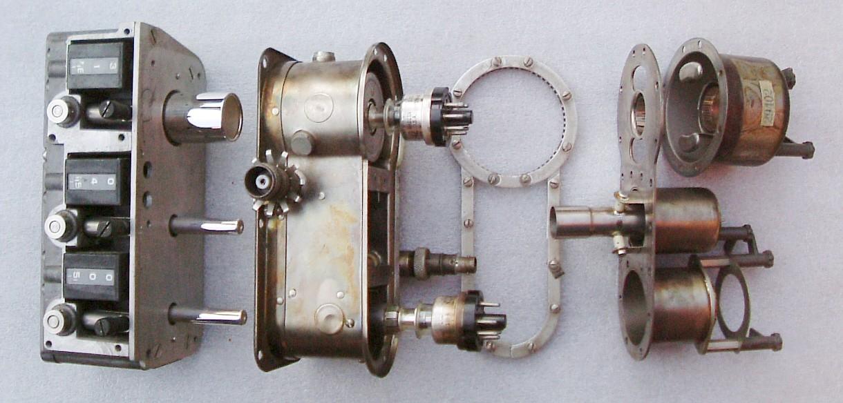
This is the RT82/APX, introduced in WWII. The self-oscillating transmitter consists of a single lighthouse tube 2C42 with an incredible pulse power output of 1kW at 1000 MHz. With a maximum duty cycle of 0.0025, the average output was 2.5W. The Transmitter 2C42, local oscillator 2C46 and the antenna tuned circuit each have a hand-tuned cavity in the combined tuning head. The relation of dial setting versus frequency in my unit is here The circuit diagrams for this unit are APX6 RF circuits and power supply
Photographs of Inside view frontside (RT82/APX6) Inside view rearside (RT82/APX6)
|
|
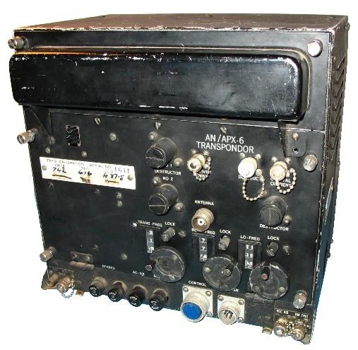
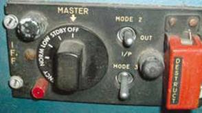
C544 / APX6 The original RT-82/APX6 had 3 charges called destructor 1, 2 and 3 , intended to distort the cavities and prevent that the real IFF frequencies were found. They could be triggered from this control panel and from a crash detector.
The RT-82 replied IFF challenges, but also primary radar impulses in conjunction with the radar receiver R-269/ APX6 in so-called Black Maria (BM) operation. When used in this manner the AN/APX-6 replied to special interrogations routed through the R-269 /APX-6, giving azimuth to the IFF reply.
|


|
The first widely used IFF transponder. |
|
VINTAGE AVIONICS |
|
AN/APX-6 IFF |
|
The APX-6 was the first widely used IFF transponder , and the first large application of lighthouse tubes. It could receive double pulses between 960 and 1150 MHz, and replied with single or double pulses, depending on the setting of the cockpit control panel. |