


|
Communications |
|
VINTAGE AVIONICS |
|
TR 1985/6/7 VHF TransceiverS 1951 |
|
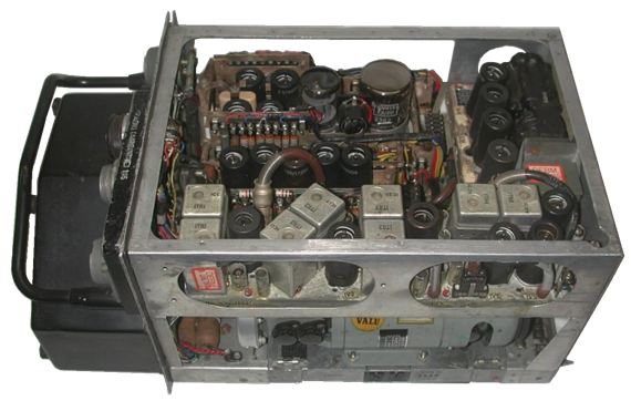
View on the TR1985. Top is the 5W transmiiter, in the middle the receiver and local oscillator, and in front the IF amplifier with the square bandfilters. The audio module / modulator is to the right (rear side of the transceiver) |
|
Military (RAF) Civil Freq range TR1985 STR.9-X.2 100 - 125 MHz TR1986 STR.9-X.3 124.5- 156 MHz TR1987 STR.9-X 115 - 145 MHz |
|
FM Communication
VHF Communication TR 1985
UHF Communication
|
|
10-channel VHF transceivers, made by STC in military and civil versions : |
|
The TR198x series VHF transceivers, made by STC, operate in anyone of 10 channels in the VHF air band. The 10 channels are preset by Xtals. After inserting Xtals, the receiver is to be tuned for maximum noise, and the transmitter for maximum light from a lamp on the antenna connector. These settings have to be made for each channel, and then stored in the mechanical selector mechanism.
The transceiver is a single superhet with 9.72 MHz intermediate frequency. The bandwidth is 80kHz ( between –6dB points) , 280kHz between the –40dB points. The sensitivity is 10uV. The transmitter provides 4W output, AM modulated. The unit is powered by 27Vdc, 7.2A ( 2.3A for filaments and 5A for the dynamotor). The heaters are parallel/series fed via an 18.9V carbon pile regulator.
The control panel is connected via an 12-wire cable and has an 11-position rotary switch which connects all wires to ground except the selected one.
Click here for the circuit diagram
In 1960, the 10-channel selector mechanism could be upgraded to a 44-channel mechanism. This was the TR 13046 with auto tuning of the RX and Tx— only the crystals should be placed. |
|
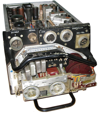
On the front side of the TR1985 you see from left to right the connectors for 27Vdc, antenna, auxiliary (?), controller, and the headset.
Below these connectors is the channel mechanism with up to 10 crystals ( 4 mounted here)
There are no connections on the rear side.
The dynamotor provides the forced air ventilation of the unit, and—via an electromagnetic clutch- the drive for the channel changing mechanism |