|
|

|
AN/APX-44 IFF transponder
This transponder was designed a few years after the ARN-21, and uses the same tubes, and the same frequencies (1030MHz uplink, 1090MHz downlink) but with a much higher bandwidth ( 6MHz) due to the shorter pulses (0.5 us)
In this unit, early PNP germanium power transistors appear from DELCO to generate the anode voltages for the 35 tubes.
The transponder receives double pulses from a secondary antenna on a ground radar. Depending on the time between these double pulses ( 3, 5 or 8us is mode 1,2 or 3) the APX44 replies with a different string of pulses. The 5 resp. 6 bit code for modes 1 and 3 are set in the cockpit. The 12 bit code for mode 2, ( aircraft ID ) is set behind the hinged door on the receiver-transmitter RT494.
The circuit diagrams can be seen here:
APX44 RF part and power supply
In 1968, an upgrade kit came to convert the APX44 into APX44B. The kit contains a new video amplifier for side-lobe suppression, and a transient limiter for the 28Vdc input.
The 914A is the civil counterpart of this transponder, also made by Wilcox. |
|
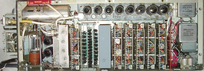
Front view of the RT494, the receiver-transmitter of the APX44. This unit has 35 tubes, 4 power transistors, and over 100 early silicon diodes.
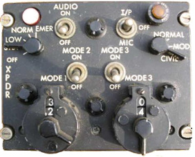
The control panel C2714 —> with mode-1 and -3 code wheels
The mode-2 code is set behind the door on the front of the RT494.
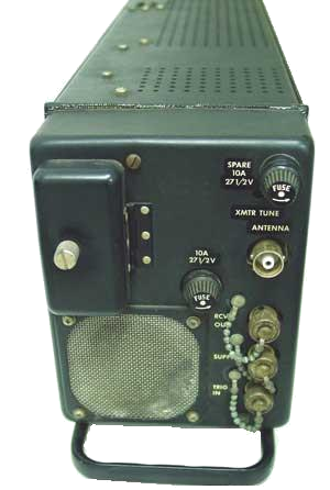
Shown below is the RT494 as seen from the right side Top left is the free running transmitter with a 2C39A in a cavity for 1kW peak RF. When transmitting a maximum of 5000 pulses/sec of 0.5us each, this is an average power of only 5W . |


|
VINTAGE AVIONICS |