

|
ARN-52 unit in Starfighter F104 format |
|
Only the modulator and power supply are solid state, all other units have only tubes. The regular ARN-52 is built in a square box with a standard 45-pin connector like the ARN21. The Starfighter version shown here has a slightly different shape to fit in the F104G Starfighter avionics bay and has two 34-pin M-series connectors. The unit was made by Standard Electric Lorenz (SEL)
Circuit diagrams are here: - RF module ( PA, oscillator/multiplier, IF amplifier and modulator) - Range circuits (Decoder, A , B and mech. module, SelfTest and Limited Search option) - Azimuth circuits ( Decoder, A, B and mech. module, magnetic amplifier) - Power supply , backplane relays, main connectors. |
|
In 1963, the ARN-21 was followed up by the ARN-52, supporting the A-A mode, built-in indicator couplers, a bidirectional azimuth search, and fast short-range search. Except for the modulator and power supply, all units still have tubes.. |


|
A tribute to its inventor, Sven H. Dodington. |
|
VINTAGE AVIONICS |
|
AN/ARN-52 TACAN |
|
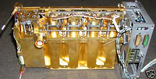
The two black modules on the top row contain the mechanical servo/synchro systems for range and azimuth. These indicator couplers match with specific indicators like the Course Deviation Indicator (ID-249 ) and Radio Magnetic Indicator ( ID-250) . The Starfighter version matches with the PHI-4 indicator. The bearing module has a synchro output to drive the CDI and RMI instruments, while the Range module has two potmeters for the autopilot and PHI-4 indicator.
The other modules on the top row are the Bearing ( -decoder , -“A” and -“B” ) modules, and the Range (-decoder, -“A” and -“B”) modules, on the lower row are the RF module, magnetic amplifier and the power supply . The large module (lower left) contains all the RF parts. The backbone of this module is the gold-plated cavities block with four 2C39A type disc triodes as drivers and final amplifier . ( Shown below in upside-down position) The cavities are pressurized and tuned with a long shaft, which also rotates 1) a turret with 126 crystals, one for each channel , 2) the multiplier tuned circuits , 3) at the far end the Preselector cavities for reception, and 4) the position feedback potmeters. Also attached to the RF module frame are on the frontside the oscillator / multiplier, and the IF amplifier, and on the rear side the (solid state) modulator and the channel motor controller. |
