


|
VINTAGE AVIONICS |
|
INSTRUMENT LANDING SYSTEMS |
|
GlideSlope Receiver Bendix GSA-8 This is a dual superhet receiver for the original glide slope frequencies 329.3 -335.0 MHz in 300kHz steps In these days, there were only 20 channels, paired with LOC channels. The first local oscillator has 10 crystals, selected by a stepper solenoid, the first IF is 51.35MHz. The second local oscillator has 2 crystals, 45.9 and 46.2MHz, followed by a second IF at 5.3MHz with 3 stages and 150kHz bandwidth. Typical is the AGC on g3 of these IF tubes. The high bandwidth was needed to handle the tolerance and drift in the transmitter frequency and local oscillator crystals. The 90Hz and 150Hz signals are filtered and rectified like in the ARN-31.
Marker Receiver Bendix MKA-7B Is a single superhet receiver for the standard marker frequency of 75 MHz The first local oscillator crystal is 70.5MHz, the IF operates at 4.5 MHz with 3 stages and 70kHz bandwidth. After AM detection , the beacon tone and (morse) identifier are available at the audio output ( 1W into 25 ohm). A second output can be tuned with an external capacitor to 400Hz or 1300Hz to drive the amber or blue lamp.
Power supply Both the GSA-8 and the MKA-7 have plug-in power supplies for either 28V only, or 115V/ 400Hz and 28V supply.
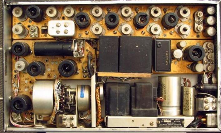
Below: inside the GlideSlope receiver. Top the IF amplifier, middle left the RF amplifier and mixer, middle right the 90Hz and 150Hz filters, bottom left HF oscillator and crystal turret with ratchet drive; bottom right: plug-in power supply, here the ac version. |
|
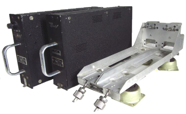
Marker and GlideSlope Receivers and twin mount |
Bendix GSA-8 GlideSlope ReceiverBendix MKA-8 Marker ReceiverUsed in civil aviation in the late fifties |
|
1958 |